Inverter Control Guide
This guide covers the battery and inverter control functionality available for each Growatt inverter model family. Not all models support the same controls — the method of control and available settings differ significantly between families.
Control Architecture Overview
The integration exposes inverter control via standard Home Assistant Select and Number entities. Controls are automatically instantiated based on which holding registers are present in the active device profile — no manual configuration is required.
Two fundamentally different control models are used across the supported inverter families:
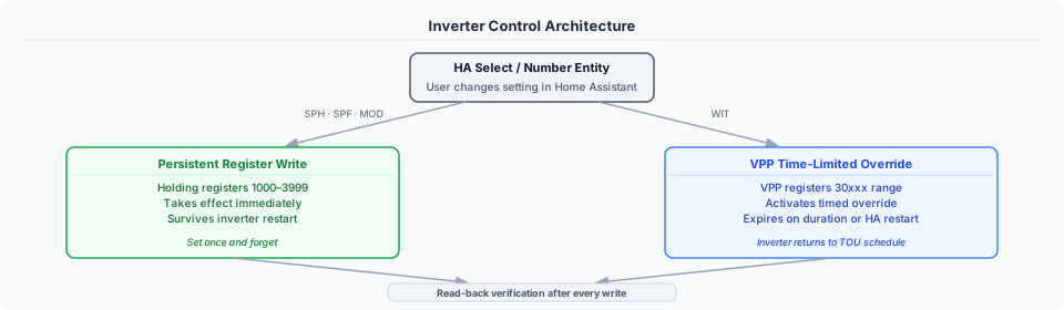
All writes use read-back verification — after writing, the integration reads the register back to confirm the value stuck. If a ShineWiFi dongle overwrites the value on the next poll cycle, a persistent notification is shown in the HA UI.
Persistent Holding Register Writes (SPH, SPF, MOD)
- How it works: Write a value to a Modbus holding register. The setting takes effect immediately and persists until changed again — it survives inverter restarts.
- When to use: Changing operating mode, charge/discharge limits, AC charge enable. Set once and forget.
- Risk level: Low. Standard Modbus write to a well-documented register.
VPP Time-Limited Overrides (WIT)
- How it works: Write a command to VPP protocol registers (30xxx range) that activates a time-limited battery override. The inverter returns to its base TOU schedule when the duration expires or HA restarts.
- When to use: Temporary battery force-charge (e.g., cheap tariff window), temporary discharge control.
- Risk level: Medium. Requires understanding of the VPP protocol. Rate limiting and conflict detection are built in.
- See also: WIT Control Guide for detailed VPP documentation.
SPH Hybrid Inverters
Applies to: SPH 3000-6000TL-BH, SPH 7000-10000TL3-BH, SPH/SPM 8000-10000TL3-BH-HU
Control method: Persistent holding register writes (1000+ range)
Control entities:
| Entity | Type | Register | Options / Range | Description |
|---|---|---|---|---|
| Priority Mode | Select | 1044 | Load First (0), Battery First (1), Grid First (2) | Sets the primary power source priority |
| AC Charge Enable | Select | 1092 | Disabled (0), Enabled (1) | Allows/prevents charging from grid |
| Discharge Power Rate | Number | 1070 | 0–100 % | Maximum battery discharge power rate |
| Discharge Stopped SOC | Number | 1071 | 0–100 % | SOC level at which discharge stops |
| AC Charge Power Rate | Number | 1090 | 0–100 % | Maximum battery charge power rate |
| AC Charge Stop SOC | Number | 1091 | 0–100 % | SOC level at which charging stops |
| System Enable | Select | 1008 | Disabled (0), Enabled (1) | System enable control (HU models only) |
| Battery First Period 1 Start | Time | 1100 | HH:MM | Charge schedule slot 1 start |
| Battery First Period 1 End | Time | 1101 | HH:MM | Charge schedule slot 1 end |
| Battery First Period 1 Enable | Select | 1102 | Disabled (0), Enabled (1) | Enable charge slot 1 |
| Battery First Period 2/3 | Time / Select | 1103-1108 | as above | Charge schedule slots 2 and 3 |
| Grid First Period 1 Start | Time | 1080 | HH:MM | Discharge/export schedule slot 1 start |
| Grid First Period 1 End | Time | 1081 | HH:MM | Discharge/export schedule slot 1 end |
| Grid First Period 1 Enable | Select | 1082 | Disabled (0), Enabled (1) | Enable discharge slot 1 |
| Grid First Period 2/3 | Time / Select | 1083-1088 | as above | Discharge schedule slots 2 and 3 |
| Battery First / Grid First 4-6 | Time / Select | 1017-1034 | as above | Extra slots - see the note below |
Two independent schedules. Battery First (1100-1108) is the charge schedule and Grid First (1080-1088) is the discharge/export schedule. They run concurrently and do not conflict - confirmed on an SPH 3600 running one of each simultaneously for several hours (#386).
The slot numbers shown match the Growatt app and Protocol V1.39. The underlying entity IDs
use an older numbering (grid_first_time_period_7/8/9 for Grid First 1-3, time_period_*
for Battery First), which is kept so existing automations continue to work.
Three independent control blocks, and none of them overrides another. This is the part that catches people out, because the entities sort alphabetically and nothing in the list says which ones belong together:
| Block | Registers | What it governs |
|---|---|---|
| AC Charge | 1090, 1091, 1092 | Charging from the grid only |
| Battery First | 1100-1108 | When the inverter is allowed to charge |
| Grid First | 1080-1088 | When it is allowed to discharge or export |
Setting one does not constrain the others. AC Charge Stop SOC (1091) at 92 % stops grid charging at 92 % and does nothing to solar charging, which will continue to 100 % - measured on an SPH-TL3 (#403). The three controls at 1090-1092 are named as one group for that reason; the name describes the register block, not an operating mode.
If you want a charge ceiling that applies to all sources on this family, there is no single register for it - Battery First scheduling is the lever.
Slots 4-6 (registers 1017-1034) are documented but may not be implemented on your firmware. They are mapped because the protocol defines them, but at least one SPH 3600 (RAAA191904/ZCBA-0004) accepts the write and immediately reverts the register. If yours does that, disable the entities - other firmware may well support them.
Verifying PV Energy Total
PV Energy Total comes from registers 91/92 and is meant to be lifetime DC harvest. On
most hardware it is: measurements from WIT, MOD, MID and an SPH all agree with the sum of
their own per-string counters to within a fraction of a percent.
On one SPH 3600 it did not. It read 23,184.7 kWh where PV1 + PV2 totalled 19,597.9 —
about 18% high — and sat within 91 kWh of that unit's AC Energy Total, i.e. it was tracking
AC generation rather than DC harvest. A second SPH 3600 of the same model, on the same
integration version, behaved normally. So the difference is per unit, most likely firmware,
and there is nothing in the protocol that declares which convention a given inverter follows
(#381).
To check your own, enable PV1 Energy Total and PV2 Energy Total — they are
disabled by default, under +N entities not shown on the device page — and compare:
| Result | Meaning |
|---|---|
| Per-string sum ≈ PV Energy Total | Normal. Either figure is your DC harvest |
| PV Energy Total well above the sum, and close to Energy Total | Your unit reports AC there. Use the per-string sum and hide PV Energy Total |
The per-string counters matched both units' own Growatt app figures exactly, so they are the reliable measure when the two disagree.
Energy sensors worth distinguishing
Three lifetime counters look similar and mean different things:
| Sensor | Registers | Measures |
|---|---|---|
| Battery Charge Total | 1058/1059 | All energy into the battery — PV and grid |
| AC Charge Energy Total | 114/115 | Grid→battery only |
| Battery Discharge Total | 1054/1055 | All energy out of the battery |
So AC Charge Energy Total is normally lower than Battery Charge Total; the difference is what came from your panels. On one reporter's system the figures were 7,099.8 kWh against 13,820.8 kWh.
Registers 112–115 carry AC charge energy on SPH because it is a "Storage Power" model. The same addresses hold warning and fault codes on MAX-class string inverters — the protocol lists both meanings side by side, selected by device class.
There is no AC Discharge Energy Total on SPH. Protocol V1.39 defines no AC-discharge counter at all; only off-grid models (SPF, SPE) have one. If you had this entity before v1.7.6 it was never populated by a register, and any value it showed was a stale artefact. It is removed automatically on upgrade. Use Battery Discharge Total instead.
House Consumption and AC Power on SPH-TL3
On SPH-TL3, House Consumption is AC output + grid import − grid export, and AC Power is the inverter's real output power (registers 35/36, W). Both are taken from the AC side:
| Sensor | Source | Why |
|---|---|---|
| AC Power | 35/36 — real power, W | 40/41 is apparent power (VA). It reads ~1 % high at several kW and ~25 % high below 1 kW |
| House Consumption | AC Power + import − export | 1037/1038 is computed by the inverter from DC-side terms, so it includes the conversion loss and reads ~10 % high |
| Power to Load | 1037/1038, unchanged | Still available, as the inverter reports it |
The AC-side figure matched an independent wallbox meter to 0.4 % across a 6.7 kW step; the load register overshot by 3.5 %. The same relationship showed on a second unit's register scan (#447).
While the battery is charging from the grid, House Consumption falls back to the load register, because that case has not yet been measured through the AC side. SPA-TL3 is not affected: it shares the register map, but its solar comes from a separate inverter, so an AC-side balance would leave that solar out.
Battery capacity from the BMS fuel gauge
Two sensors report what the battery's own gauge measures, rather than what the inverter infers. Available on SPH-TL3 and SPH 8000-10000 HU, where the BMS block is mapped.
| Sensor | Register | Measures |
|---|---|---|
| Battery Remaining Capacity | input 1091 | Charge left in the pack, in Ah |
| Battery Full Charge Capacity | input 1092 | Usable capacity at full charge, in Ah |
Two things they are good for. Remaining ÷ Full is the gauge's own state of charge, which can differ from the reported SOC percentage — the inverter's figure is sometimes smoothed or clamped, and the gauge's is not. And Full Charge Capacity falls as the pack ages, so comparing it against the nameplate figure shows real degradation rather than the SOH estimate.
Amp-hours, not kWh
The gauge measures charge, so these are reported in Ah. Converting to kWh would mean multiplying by a pack voltage that itself moves with state of charge, producing a number that looks authoritative without being measured anywhere.
The scale comes from the ESS Protocol, which documents these registers in units of 10 mAh, and is confirmed on hardware: an SPH-TL3 with 4x Growatt ARK 2.5H-A2 in series — 50.0 Ah at 204.8 V, 10.24 kWh nameplate — reports a Full Charge Capacity of 52.50 Ah, or 105% of nameplate (#403).
A gauge reading slightly above the nameplate is normal: modules are rated conservatively. Reading well below it is the signal that matters, and it is what degradation looks like.
Note that these are input registers. Holding 1091 and 1092 at the same addresses are AC Charge Stop SOC and AC Charge Enable — an overlap that runs through this whole protocol.
Notes:
- All SPH variants share the same 1000+ register range — controls apply across 3–6kW, 7–10kW, and HU variants automatically.
- Time periods use HHMM format: 530 = 05:30, 2300 = 23:00.
- Controls are polled on every coordinator update and reflected in Home Assistant state without restart.
A second physical battery pack — Battery 2 sensors
WIT, MOD and MID hybrids can run more than one battery stack (e.g. two Growatt APX units), each wired to its own register cluster — 31300-31399 for pack 2, mirroring the primary pack's own 31200-31299. Ten Battery 2 sensors exist for this (Voltage, Current, Power, SOC, SOH, Temperature, and Charge/Discharge Energy Today/Total), and Battery 3 for a third stack on models that support it.
On an install with more than one pack, they appear disabled — enable them from the entity's settings.
On a single-pack install, they do not appear at all, not even as a disabled or
unavailable entity — there is nothing to enable. Creation itself is gated on the pack's own
voltage register answering above 0 at startup, not just the value shown, so a profile with
one pack never creates the entity in the first place (confirmed via a debug log showing the
second cluster's block reading successfully while battery2_* remained entirely absent from
both the entity registry and the coordinator data — #454).
These are not summed into the main Battery Power/SOC/etc. sensors. Two packs of different capacity don't average or add meaningfully at the SOC/voltage level, so each pack's figures stand on their own — add Battery Power and Battery 2 Power yourself in a template or the Energy dashboard if you want a combined view.
Confirmed on a MID 25kTL3-XH with a 10 kWh and a 20 kWh APX pack (#451) — reading Battery 2 Power recovered the second pack, which had been read from the inverter and discarded before this was wired up.
SPH-TL3: AC Voltage R/S/T are line-to-line, not phase voltages
On the SPH-TL3 profiles the registers the protocol labels as phase voltage return line-to-line voltage - about 400 V on a 230/400 V supply, not 230 V. Two SPH 10000TL3 BH-UP owners have confirmed it, and one settled it directly by reading those registers against the VPP registers documented as line voltage, seconds apart:
38  ac_voltage_r   404.1 V      31106 (L1-L2)   404.0 V
42  ac_voltage_s   408.0 V      31107 (L2-L3)   407.7 V
46  ac_voltage_t   390.4 V      31108 (L3-L1)   390.5 V
The three per-phase AC Power entities are not readings. On both inverters the S and T power registers are empty, so this integration computes all three from voltage times current - and because the voltage is line-to-line, they come out about √3 too high. The inverter fills only the R register, which holds total output rather than a per-phase value.
They are left as they are for now: dividing by √3 would invent a phase voltage that is only correct on a perfectly balanced supply. For per-phase voltage, use a meter - the figures in the Growatt portal come from one. From v2.0.4-b15 the same values are also published, correctly labelled, as AC Voltage RS/ST/TR (#442, #447).
SPF Off-Grid Inverters
Applies to: SPF 3000-6000 ES PLUS
Control method: Persistent holding register writes (0–97 range)
Control entities:
| Entity | Type | Register | Options / Range | Description |
|---|---|---|---|---|
| Output Priority | Select | 1 | SBU (0), SOL (1), UTI (2), SUB (3) | Output source priority |
| Charge Priority | Select | 2 | CSO (0), SNU (1), OSO (2) | Battery charge source priority |
| BLU/LBU Mode | Select | 116 | BLU (0), LBU (1) | Which load PV energy serves first. Firmware 100.08/101.07 and later only |
| AC Input Mode | Select | 8 | APL (0), UPS (1), GEN (2) | AC input mode (appliance / UPS / generator) |
| Battery Type | Select | 39 | AGM (0), FLD (1), User (2), Lithium (3), User 2 (4) | Battery chemistry (⚠️ set with caution) |
| Max Charge Current | Number | 34 | 10–100 A | Total charging current, solar + utility combined (LCD Program 02) |
| Bulk Charge Voltage | Number | 35 | 48.0–58.4 V | C.V. charging voltage (LCD Program 19). Disabled by default |
| Float Charge Voltage | Number | 36 | 48.0–58.4 V | Floating charging voltage (LCD Program 20). Disabled by default |
| AC Charge Current | Number | 38 | 0–80 A | Max charging current from AC/grid (LCD Program 11) |
| Generator Charge Current | Number | 83 | 0–80 A | Max charging current from generator. Unavailable on models that answer 0xFFFF — they have no such setting |
| Battery to Utility Switchover | Number | 37 | 0–100 % (Lithium) / 20–64 V (Lead-acid) | SOC/voltage to switch from battery to utility |
| Utility to Battery Switchover | Number | 95 | 0–100 % (Lithium) / 20–64 V (Lead-acid) | SOC/voltage to switch back from utility to battery |
| Battery Cut-Off | Number | 82 | 0–100 % (Lithium) / 20–64 V (Lead-acid) | Undervoltage cut-off: how deep the battery discharges before the inverter stops drawing from it |
Output Priority options:
- SBU — Solar → Battery → Utility (battery-first, self-consumption focused)
- SOL — Solar → Utility → Battery (solar-first, grid backup)
- UTI — Utility → Solar → Battery (grid-first, battery preserved)
- SUB — Solar & Utility → Battery (combined source charging)
BLU/LBU Mode options (register 116, added by firmware 100.08/101.07):
- BLU — Battery → Load → Utility: PV charges the battery before serving the load
- LBU — Load → Battery → Utility: PV serves the load before charging the battery
This is a different setting from Output Priority above, which picks the source; this one
picks what PV energy does first. The protocol table calls the register uwLoadFirst, and
the same register on SPE carries a third ordering (LUB) that SPF does not have — so
the control is offered with two options on SPF and three on SPE. Confirmed on an SPF 6000 ES
Plus by writing each value and reading the inverter's display back
(#437).
Charge Priority options:
- CSO — Solar first, grid only when solar insufficient
- SNU — Solar and grid simultaneously
- OSO — Solar only, no grid charging
Max Charge Current vs AC Charge Current. Max Charge Current (34) is the total across both chargers — solar plus utility. AC Charge Current (38) limits only the utility side. If you set the total below the AC limit, the inverter applies the total to the utility charger as well, so 34 can quietly override 38.
Bulk and Float Charge Voltage are disabled by default, and only work on a self-defined battery type. These are the only controls in this integration where a wrong value affects hardware rather than a reading: the inverter rejects anything outside 48.0-58.4 V, but an in-range value that is wrong for your battery chemistry will be accepted and applied. They are created disabled so enabling them is a deliberate step - **Settings > Devices & Services
Growatt Modbus > entities**, then enable the one you want. They are on the Battery device with the other charge settings (up to v2.0.6-b3 they were on the Inverter device) (#468).
Both correspond to LCD Programs 19 and 20, which the manual marks as settable only when Program 5 (battery type) is a self-defined option. The entities are therefore unavailable on AGM, Flooded and Lithium. The integration reads your existing values and never writes a default - a value changes only when you move the control (#384).
Bulk cannot be set below Float, and the two controls enforce that on each other. Bulk is the constant-voltage charging stage and Float the maintenance stage, so a bulk voltage below float is meaningless and the firmware rejects it.
It rejects it silently: the write is acknowledged, the register reverts, and the integration's read-back check then reports "settings are being reverted" - which reads as a fault in the integration or interference from the Growatt cloud, rather than as a request the inverter was right to refuse. One reporter spent time chasing exactly that on a system with no datalogger attached (#387).
So the Bulk slider will not go below the current Float value, and the Float slider will not go
above the current Bulk value. Setting them through number.set_value from a script or
automation - which bypasses the slider limits - fails with a message saying what the limit is
and why, instead of appearing to succeed.
Equal values are allowed. To move both, change them in the order that keeps the pair valid: raising both means raising Bulk first, lowering both means lowering Float first.
Battery to Utility Switchover cannot be set above Utility to Battery Switchover, and the two controls enforce that on each other in the same way. The inverter switches back to the battery at a higher level than the one at which it switched to the grid, and silently reverts a write that would reverse them: an SPF 6000 ES Plus took 21-25 % for Battery to Utility only after Utility to Battery had been raised above it (#471). To raise both, raise Utility to Battery first; to lower both, lower Battery to Utility first.
Max Charge Current is unavailable when Battery Type is Lithium. The inverter does not allow it to be set in that mode — the BMS takes over charge current control — so the entity is withheld rather than offered and ignored. Range and behaviour are confirmed on an SPF 6000ES Plus; smaller units in this family accept a lower maximum, and a value above what your model allows will be rejected by the inverter and the entity will revert (#376).
Notes:
- SPF is an off-grid inverter — there is no grid export. The grid is treated as an AC input source for charging/backup.
- battery_type (register 39) controls charging voltage thresholds. Changing this incorrectly can damage batteries. Verify your battery chemistry before writing.
- bat_low_to_uti and ac_to_bat_volt operate in different units depending on battery type: percentage (0–100%) for Lithium, voltage (20.0–64.0V) for lead-acid types. This is why they are named Switchover rather than SOC or Voltage — the unit shown on the entity follows your battery type, so a name claiming either would be wrong for half of you. Read the unit on the entity itself.
!!! tip "If a dashboard card still shows the old unit, re-add the card"
    The unit follows your battery type live, so changing the type switches these entities
    between **%** and **V** without a restart. An existing dashboard card can keep
    rendering the old unit, because the card caches it rather than reading it back.

    Removing the card and adding it again fixes it. Nothing is wrong with the entity —
    check its value on the device page to confirm. Reported by @eugeniodb on
    [#428](https://github.com/0xAHA/Growatt_ModbusTCP/issues/428).
Grid Connection Status on SPF/SPE reports what the inverter is running on, not whether mains is present. It reads the off-grid status code: AC charging in any combination, or bypassing the AC input straight to the load, is On-grid; discharging the battery, PV charging, or PV charging while discharging is Off-grid. Standby, Fault and Flash say nothing either way and fall back to the AC input voltage. So an SPF on battery-first priority can show Off-grid with 230 V at its input - the utility is there, and the inverter is choosing not to use it. If you want to know whether mains is up, use Grid Voltage (#443).
WIT Commercial Hybrid Inverters
Applies to: WIT 4000-15000TL3-X
Control method: VPP time-limited protocol (30xxx registers + legacy 2xx registers)
Control entities:
| Entity | Type | Register | Options / Range | Description |
|---|---|---|---|---|
| Work Mode | Select | 202 | Standby (0), Charge (1), Discharge (2) | Remote battery command mode |
| Active Power Rate | Number | 201 | 0–100 % | Power level for charge/discharge command |
| Export Limit | Number | 203 | 0–20000 W | Export limit in watts (0 = zero export) |
| Control Authority | Select | 30100 | Disabled (0), Enabled (1) | VPP master enable switch |
| VPP Export Limit Enable | Select | 30200 | Disabled (0), Enabled (1) | Enable VPP export limitation |
| VPP Export Limit Rate | Number | 30201 | -100–+100 % | Export power rate (positive=export, 0=zero export) |
| Remote Power Control | Select | 30407 | Disabled (0), Enabled (1) | Enable timed charge/discharge override |
| Remote Control Duration | Number | 30408 | 0–1440 min | Duration for remote power control override |
| Remote Charge/Discharge Power | Number | 30409 | -100–+100 % | Power level (negative=discharge, positive=charge) |
| VPP AC Charge Enable | Select | 30410 | Disabled (0), PV priority (1), AC priority (2) | Whether the battery may charge from the grid, and what takes priority |
The seven VPP controls (30100, 30200-30201, 30407-30410) go unavailable when their register block does not answer a poll. Those blocks are read best-effort, because not every firmware implements them, and a block that is missed leaves the integration with no reading rather than a stale one. An occasional flick to unavailable is a dropped Modbus frame; permanently unavailable means your firmware does not implement the block. In neither case is a "Disabled" or 0 shown that the inverter did not report (#370, #409).
Important notes:
- WIT uses a time-limited override model. Commands via registers 30407–30409 expire after the configured duration or when HA restarts. The inverter then returns to its TOU schedule default.
- Register 30476 (priority_mode) on WIT shows the base TOU mode. Writability varies by model - it was documented as read-only, but has been written successfully for months on a WIT 8000TL3-HU (#353). The TOU Default Mode control writes it; if your model rejects the write, use the inverter display or Growatt app instead.
- Rate limiting is built in to prevent command flooding.
- Conflict detection prevents simultaneous charge + discharge commands.
Battery Power can read a tenth of the truth, and how that is handled. WIT firmware comes in two variants: most report battery power in tenths of a watt, as the VPP specification says, and some report it in whole watts. The integration works out which by comparing the power register against battery voltage x current, and needs three consistent readings above 500 W before it commits - a single decision taken at low load once latched the wrong answer and produced 40 kW readings on a 6.5 kW battery (#406).
Two things follow from that, both fixed in v2.0.4-b12 (#434):
- A confirmed scale is remembered and applied from the first poll of the next session. Before this, anything that rebuilt the Modbus client - a reload, and on at least one gateway a dropped connection - lost it, and the correct scale could only be re-earned once the battery was working above 500 W. Overnight it never is, so a tenth-of-the-truth reading could persist until morning.
- Battery Power goes unknown rather than wrong in the window where voltage x current has already contradicted the scale in force but the replacement is not yet confirmed. A gap in the graph is recoverable; a plausible wrong number goes into long-term statistics and cannot be told apart from a real one afterwards. House Consumption and Grid Power follow it when they would otherwise have been worked out from the withheld battery figures - before v2.0.4-b15 Battery Power showed 0 W in that window, which is what an idle battery really reads, and the two derived sensors quietly left the battery out.
If a remembered scale is ever wrong, real load overrules it: detection keeps running, and three consistent samples of the other scale replace it. Changing profile discards it outright.
See WIT Control Guide for full protocol documentation.
MOD Three-Phase Hybrid Inverters
Applies to: MOD 6000-15000TL3-XH and MID 11000-30000TL3-XH (VPP V2.01, DTC 5400)
Control method: Persistent writes to the 3000-range GEN4 registers.
Controls
| Entity | Type | Register | Options / Range | Description |
|---|---|---|---|---|
| Allow Grid Charge | Select | 3049 | Disabled (0), Enabled (1) | Permits charging from the grid. Must be Enabled for time-of-use writes to persist |
| Charge Power Rate | Number | 3047 | 1–100 % | Battery charge power limit |
| Charge Stopped SOC | Number | 3048 | 0–100 % | SOC at which charging stops, from any source |
| Discharge Power Rate | Number | 3036 | 0–100 % | Battery discharge power limit |
| Discharge Stopped SOC | Number | 3067 | 1–100 % | SOC at which discharging stops |
| Grid Charge Stopped SOC | Number | 3312 | 0–100 % | SOC at which charging from the grid stops. See below |
| Time Period 1–9 Priority | Select | 3038–3058 | Load / Battery / Grid First | Priority for each time-of-use slot |
| Time Period 1–9 Enable | Select | 3038–3058 | Disabled, Enabled | Enable each slot |
| Time Period 1–9 Start / End | Time | 3038–3059 | 00:00–23:59 | Slot start and end times |
Two charge-stop settings, and they are not the same
Charge Stopped SOC (3048) applies to charging from any source. Grid Charge Stopped SOC (3312) applies only to charging from the grid, and the lower of the two wins.
This catches people out. On one system 3312 sat at 55 % while 3048 was 100 %, silently capping grid charging for two days (#372). Growatt exposes 3312 in neither the ShinePhone app nor the web portal, so if grid charging stops short of your configured limit, check this entity.
Registers 1090 and 1092 are not available on this hardware
Earlier versions offered AC Charge Power Rate (1090) and AC Charge Enable (1092) on MOD. The entire holding block 1000–1124 is unimplemented on this family — a full sweep read zero across all 125 registers, and writes are rejected outright with Modbus exception 2 (#371).
Both were removed. Use Charge Power Rate (3047) and Allow Grid Charge (3049) instead; both are confirmed working. If you had automations pointing at the old entities, they will have been removed on upgrade.
Peak shaving and demand management (read-only)
These are configured in the Growatt web portal and shown here for visibility. They are diagnostic entities, and appear in no public Growatt protocol document — the mappings were established by changing each value in the portal and reading the register back (#372).
| Entity | Register | Description |
|---|---|---|
| Import Limit | 3307 | Demand-management import ceiling (kW) |
| Export Limit | 3308 | Demand-management export ceiling (kW) |
| Peak Shaving Reserve SOC | 3310 | Charge held back for peak shaving (%) |
| AC Charge Max Power | 3311 | Ceiling on grid charging power (kW) |
These report what peak shaving is configured to use, not whether it is running. On the unit these mappings came from, Peak Shaving Enable reads Disable while all five registers hold plausible configured values. A populated cluster therefore says the settings exist, not that the feature is in force (#372).
These also apply to MID. The MID 11-30KTL3-XH profile loads the same register map, so the entities appear there too — the profile name does not tell you which family a register cluster reaches.
The three kW limits are unavailable until peak shaving has been configured. When the feature has never been set up, those registers hold a ceiling rather than a zero — 30000 or 65535, which would render as 3000 kW and 6553.5 kW. The integration publishes nothing instead, so an unavailable entity here means "not configured in the portal", not a communication problem (#380).
Reserve SOC is the exception and is always shown. An SOC has no implausible ceiling to give it away — 50 % reads identically whether you set it or the factory did — so there is no way to tell configured from unset, and guessing would be worse than showing the value.
VPP remote power control (read-only)
MOD TL3-XH does support VPP remote power control — this was measured on hardware (#373) — but the controls are not exposed for writing yet. The state is available as disabled-by-default diagnostic entities: VPP Control Authority (30100), VPP Remote Power Control (30407), VPP Commanded Power (30409) and VPP Last Setpoint (30474).
Why writing is not exposed
The commanded power is a target, not a limit. At 100 % with insufficient solar, the inverter climbed toward the setpoint and drew 912 W from the grid — while Allow Grid Charge was Disabled. At lower percentages only downward limiting is visible, which makes it look like a cap.
The duration expires but the registers do not clear. After a 2-minute command the power constraint released at ~128 s while all three registers stayed set for the full observation. You cannot tell from these values whether control is currently active.
Writable controls need a guard against commanding more power than solar can supply. Until that exists, exposing them would let an automation import from the grid while the user believes grid charging is switched off.
Battery monitoring sensors available:
| Sensor | Register | Description |
|---|---|---|
| Battery SOC | 3171 | State of charge (%) |
| Battery SOH | 1096 | State of health (%) |
| Battery Voltage | 3169 | Battery voltage (×0.01 V) |
| Battery Current | 3170 | Battery current (×0.1 A) |
| DC-DC Temperature | 3176 | Battery-side DC-DC stage temperature (×0.1 °C). Not the pack temperature — see #362 |
| Battery Charge Power | 3178/3179 | Charge power (×0.1 W) |
| Battery Discharge Power | 3180/3181 | Discharge power (×0.1 W) |
| Battery Charge Today | 3129/3130 | Energy charged today (kWh) |
| Battery Discharge Today | 3125/3126 | Energy discharged today (kWh) |
| Battery Charge Total | 3131/3132 | Lifetime charge energy (kWh) |
| Battery Discharge Total | 3127/3128 | Lifetime discharge energy (kWh) |
| AC Charge Energy Today | 3133/3134 | Grid→battery energy today (kWh) |
| AC Charge Energy Total | 3135/3136 | Grid→battery lifetime energy (kWh) |
MIN Grid-Tied Inverters (no battery)
Applies to: MIN 3000-6000TL-X, MIN 7000-10000TL-X — genuinely grid-tied, no battery port.
Control: No battery control available. These models have no battery management registers.
Available controls: None beyond the universal on_off (register 0) and active_power_rate (register 3) which are present on all models but not exposed as control entities by default.
MIN TL-XH Hybrid (with a battery — e.g. APX)
Applies to: MIN TL-XH 3000-10000, V2.01, DTC 5100, with a battery attached.
Control method: Persistent writes to V1.39 registers, same family as MOD/MID above but a different address set. Confirmed on hardware, not assumed from the register table (#400 — @GoncaloRibeiro11's Battery First selection was independently confirmed by the house drawing its full load from the grid while solar charged the battery).
Controls
| Entity | Type | Register | Options / Range | Description |
|---|---|---|---|---|
| Priority Mode | Select | 3018 | Load First (0), Battery First (2), Grid First (3) | Note the encoding: 1 is not used, unlike the 0/1/2 scheme on SPH/MOD/MID |
| Allow Grid Charge | Select | 3049 | Disabled (0), Enabled (1) | Permits charging from the grid; disabled by default pending write confirmation |
| Charge Power Rate | Number | 3047 | 1–100 % | Battery charge power limit when Battery First is active |
| Charge Stopped SOC | Number | 3048 | 0–100 % | SOC at which charging stops when Battery First is active |
| On-Grid Discharge Stop SOC | Number | 3067 | 1–100 % | SOC at which on-grid battery discharge stops |
| Off-Grid Discharge Stop SOC | Number | 30475 | 10–100 % | SOC at which off-grid battery discharge stops (VPP V2.01) |
SOC-limit writes on DTC 5100 depend on the firmware build
On a MIN 4200TL-XH with an APX battery, firmware build ALBA13 silently refused
SOC-limit writes. There was no Modbus exception, but an immediate read-back over both
FC06 and FC16 still held the old value, and the same change made in ShinePhone reverted
too. Growatt then updated the same inverter to ALBA18010122, and registers 3048 and
3067 accepted changes. Register 30475 takes changes on that build as well: 16 → 20 → 16,
each still in place five minutes later
(#400,
#460).
If a write will not stick on your unit, check the firmware build first. It is shown in brackets after the firmware version on the inverter's device page. It is not simply old firmware: a unit on the older ALba10 build accepted a 3048 write.
The app's "Discharge Power" setting has no confirmed register. Holding 3066 read 0 while the app showed 100 %, and writes to 3066 were rejected over both FC06 and FC16. 30474 is the last remote power command, not a persistent limit.
Do not leave VPP Control Authority enabled without an active command
On the measured MIN 4200TL-XH, 30100 = 1, 30407 = 0 and 30411 = 0 left the
inverter in VPP standby: Load First was selected, but the grid supplied most of the
house and the battery discharged only about 102 W. Clearing Control Authority
(30100 = 0) restored Load First immediately, and battery discharge rose to about
1,348 W.
To clear it, run Set Battery Mode with mode release, which needs only register
30100 and so works on MIN TL-XH, or enable the Control Authority select (disabled by
default) and set it to Disabled. See Actions.
Waking a sleeping APX battery (MIN TL-XH, VPP 2.01 only)
| Entity | What it does |
|---|---|
button.<name>_wake_apx_battery |
Sends a short, bounded charge request to wake a sleeping APX pack |
Disabled by default, and only created on MIN_TL_XH_3000_10000_V201 — the one profile
this has been hardware-tested against (a MIN 4200TL-XH, DTC 5100, APX S0). An APX pack can
go to sleep in a way that changing Priority Mode alone does not wake; this button requests a
5%, one-minute VPP direct-charge pulse instead, held for 12 seconds, then reverses itself —
clearing the pulse and restoring whatever VPP authority, branch selection and parameters
were active before the press, in the order that keeps a partial failure safe rather than
leaving a larger old setpoint re-armed behind a pulse that never cleared
(#400).
If your inverter uses VPP 2.03 rather than 2.01, this button does not appear — mode 2
(2.03's wake value) is silently normalised back to 1 on 2.01 firmware, so the two are not
interchangeable, and only the 2.01 behaviour has been confirmed on hardware so far.
Time-of-use periods (MIN TL-XH)
Nine TOU periods, each with Start, End, Priority (Load / Battery / Grid) and Enable entities: registers 3038-3045 and 3050-3059, the "Time 1-9 (xh)" block of Protocol V1.39, packed the same way as on MOD TL3-XH. A MIN 4200TL-XH read period 1 exactly as ShinePhone had set it, including end-time changes of one minute (#400).
Disabled by default. Reading is confirmed; writing from Home Assistant has not been tested on this model yet. Enable the entities you need on the device page. If a change doesn't stick, report it on #400.
Allow Grid Charge (holding 3049) is also disabled by default while its write is being
validated. Its read mapping is confirmed against consecutive ShinePhone changes: Disabled
returned 3049 = 0, then Enabled returned 3049 = 1. This is a separate holding-register
address from input registers 3049/3050, which carry today's energy.
Battery Working Status (MIN TL-XH)
VPP input register 31001: Standby, Disconnected, Charging, Discharging, Fault or Upgrade. An APX battery that has gone to sleep shows Disconnected, which makes this the sensor to watch for the sleep described above (#460).
Battery pack sensors (MIN TL-XH)
Four diagnostic sensors describe the pack from VPP input registers 31225-31228: Battery Clusters, Battery Modules per Cluster, Battery Module Rated Voltage and Battery Module Rated Capacity. A MIN 4200TL-XH with two APX modules read one cluster of two modules, each rated 51.2 V and 100.0 Ah (#460). The protocol has no register for the battery's brand, so the integration cannot tell an APX from an ARK.
MIN TL-XH2 Hybrid (VPP only)
Applies to: MIN TL-XH2 3000-10000, DTC 5100. Select the MIN TL-XH2 profile by hand: the XH2 shares DTC 5100 with the first-generation TL-XH but answers only the VPP registers.
Control method: VPP V2.01 registers. Validated on a MIN 3000TL-XH2 with an APX 5.0M-B3, each by a real change, a read-back and the inverter acting on it (#461).
| Entity | Type | Register | Options / Range | Description |
|---|---|---|---|---|
| Charge Stop SOC | Number | 30404 | 10–100 % | SOC at which battery charging stops |
| On-Grid Discharge Stop SOC | Number | 30405 | 10–100 % | SOC at which on-grid battery discharge stops |
| Remote Power Control Enable | Select | 30407 | Disabled / Enabled | Starts or stops a remote charge/discharge command. Disabled by default |
| Remote Power Control Charging Time | Number | 30408 | 0–1440 min | Duration of the command. Disabled by default |
| Remote Charge And Discharge Power | Number | 30409 | -100 to 100 % | Positive charges, negative discharges. Disabled by default |
| VPP AC Charge Enable | Select | 30410 | Disabled / PV priority / AC priority | Allows charging from the grid. Disabled by default |
With these mapped, the Set Battery Mode action works on the XH2. charge at 25 % charged
at about 600 W, a quarter of the 2.5 kW the battery reports as its maximum, and release
returned the inverter to its own mode. discharge has not been tried yet, and hold writes
the VPP time-of-use registers (30411 onward), which have not been tested on this model. See
Actions. Run release when you are done, for the same
reason as on MIN TL-XH above.
Sensors the XH2 has no register for are not created. AC charge energy, the V1.39 fault and warning codes, the safety diagnostics, Priority Mode and similar sensors all come from ranges the XH2 does not implement. Battery Temperature is also left out: its documented register (31223) reads 0 on every XH2 seen so far. On earlier versions they showed a constant 0; from v2.0.5-b17 they are removed.
MIC Micro Inverters
Applies to: MIC 600-3300TL-X
MIC is a grid-tied micro inverter with no battery, so there is no battery control. One
inverter setting is exposed, on the MIC MIN-range profile (MIC_2500_6000TL_X_MIN_RANGE) only.
Number Entities
| Entity | Register | Range | Description |
|---|---|---|---|
| PV Startup Voltage | Holding 17 (×0.1 V) | 50.0–550.0 V | PV voltage the inverter waits for before connecting to the grid. Factory default depends on the model: 50.0 V on a MIC 2000TL-X; Growatt datasheets give 80 V for the MIC 2500-3300TL-X |
What it's for: with a single high-voltage panel, the inverter can connect at dawn before the panel can carry the load. It then drops out, recovers and reconnects, over and over, until the light is strong enough. The same happens at dusk. Raising the startup voltage makes it wait until the panel can hold the connection. Keep it comfortably below your panel's (or string's) open-circuit voltage (Voc), or the inverter will never start. The range is the inverter's MPPT window; the right value for you depends on your panels.
Summary Table
| Model Family | Battery Control | Control Method | Select Entities | Number Entities |
|---|---|---|---|---|
| SPH (3–10kW) | Yes | Persistent writes | Priority Mode, AC Charge Enable, Time Period Enables (×3), System Enable (HU) | Discharge Rate, Discharge Stop SOC, Charge Rate, Charge Stop SOC, Time Period Start/End (×3) |
| SPF ES PLUS | Yes | Persistent writes | Output Priority, Charge Priority, AC Input Mode, Battery Type | Max Charge Current, AC Charge Current, Gen Charge Current, Battery→Utility Switchover, Utility→Battery Switchover |
| WIT (4–15kW) | Yes (timed) | VPP overrides | Work Mode, Control Authority, VPP Export Limit Enable, Remote Power Control | Active Power Rate, Export Limit, VPP Export Rate, Remote Duration, Remote Power |
| MOD / MID TL3-XH | Yes | Persistent writes | Allow Grid Charge, Time Period Priority/Enable (×9) | Charge Rate, Charge Stop SOC, Grid Charge Stop SOC, Discharge Rate, Discharge Stop SOC, Time Period Start/End (×9) |
| MIN (no battery) | No | — | — | — |
| MIN TL-XH (with battery) | Yes | Persistent writes | Priority Mode, Allow Grid Charge and TOU Priority/Enable (grid charge and TOU disabled by default) | Charge Rate, Charge Stop SOC, Discharge Stop SOC (plus TOU Start/End times ×9) |
| MIN TL-XH2 | Yes (timed) | VPP overrides | Remote Power Control Enable, VPP AC Charge Enable | On-Grid Discharge Stop SOC, Remote Power Control Charging Time, Remote Charge And Discharge Power |
| MIC | No | Persistent writes | — | PV Startup Voltage (MIC MIN-range profile) |
Turning the inverter on and off
| Entity | What it does |
|---|---|
switch.<name>_inverter_power |
Remote on/off for the inverter |
switch.<name>_ac_output |
Off-grid models (SPF, SPE) instead: enables or disables the AC output |
Disabled by default on every model, so nobody switches an inverter off by accident — enable it under the inverter device's entity settings. Off-grid owners especially: turning AC Output off cuts power to everything the inverter supplies.
On MIN TL-X the switch shows the inverter's real state, read each poll while the switch
is enabled. That register was confirmed on a real unit to read 0 while off and 1 while
on, so a change made from ShinePhone or the front panel shows here too.
Everywhere else it shows the last command sent, not a reading, and offers both actions rather than a toggle. Growatt documents the register as write-only on most families, so a read is only trusted once a real unit has been seen to read back both states.
On grid-tied models it also shows on whenever the inverter reports Normal, since a running inverter must be switched on. It cannot infer off the same way: Waiting is what an inverter reports both when switched off and at night. Otherwise it starts as unknown after a restart until you use it.
Each protocol family encodes on/off differently, and the integration picks the right one from your profile:
| Family | Register | What is written |
|---|---|---|
| MIN, MID, MOD, SPH, SPA, TL-XH, WIT (V1.39) | holding 0 | 1 on, 0 off. The battery converter codes (3/2) are never used |
| MIC, TL3-S (legacy V3.14) | holding 0 | Low byte on/off only. The high byte is auto start — whether the inverter comes back after a power cut — and is read first and written back unchanged |
| SPF, SPE (off-grid) | holding 0 | High byte AC output (0x0000 on, 0x0100 off); the low byte is read first and kept |
| MIN TL-XH2 (VPP only) | holding 30101 | 1 on, 0 off. Not stored — the inverter returns to on after a reboot |
On the two read-first families, if the register cannot be read nothing is written; guessing the other byte is the mistake the read exists to avoid.
Confirmed on hardware for MIN TL-X and TL3-S only
The encodings above come from Growatt's protocol documents. So far a MIN TL-X has been
switched off and back on through this switch, reading 0 and 1 as expected, and a
TL3-S went to Waiting when switched off and ran its start-up sequence when switched
back on. On
MIN TL-XH2 in particular, other VPP controls are known to need control authority (30100)
before they act; the switch does not grant it, so 30101 may be ignored there. If you test
another model, please report what register 0 (or 30101) reads while off and while on
(#432) - that is what lets it
show the real state on your model too.
Keeping the inverter's clock accurate
Time period schedules run against the inverter's own clock, not Home Assistant's. That clock drifts — one SPH was two minutes out, which made a 13:00 export window start at 13:02.
A whole-hour offset is a timezone, not drift — and a sync will not hold
If the notification says the clock is almost exactly one hour out, the inverter's clock is being set to a different zone rather than drifting. The usual cause is the plant timezone in the Growatt portal, which offers fixed UTC offsets with no daylight-saving zones — correct in winter, an hour out in summer — and your datalogger pushes that to the inverter.
Pressing Inverter Clock Sync works and is then overwritten at the datalogger's next push. A ShineWiLan-X2 has been captured writing the inverter's time registers (holding 45–50) in bursts: none for several hours, then about every five minutes for an hour (#458). What triggers a burst is not known yet. Either way a scheduled sync is not a workaround: it fights the datalogger indefinitely and burns EEPROM writes for nothing.
Before v2.0.5-b11 there was a second cause: on a host whose system clock runs in UTC
(Docker without a TZ setting, for example) the check compared against the host's time
rather than Home Assistant's, and reported the whole UTC offset as drift. Update before
concluding it is the datalogger.
If your zone observes daylight saving and the portal has no entry for it, there is
nothing to correct. Set Clock Drift Warning to 0 in the integration's options to
turn the notice off, or raise it above the offset
(#439).
Two entities cover it, both on the inverter device under Diagnostic, and both disabled by default — enable them in the entity settings if you want them:
| Entity | What it does |
|---|---|
sensor.<name>_inverter_clock |
The inverter's own clock as readable local time, e.g. 2026-08-26 14:32:05 |
button.<name>_inverter_clock_sync |
Sets the inverter's clock from Home Assistant's, on press |
They are off by default for different reasons. The sensor costs one extra register read on every poll, which is not free on a gateway that needs small blocks — nothing is read at all until you enable it. The button writes six holding registers per press, and those are very likely EEPROM-backed with a finite write budget (#392), so it is not something to leave where it can be pressed absent-mindedly.
Off-grid (SPF/SPE) gets both the sensor and the button, the same as every other
profile. An SPF 5000 ES read against a known-good clock returned 45: 2026, 46: 9, 47: 14,
48: 8, 49: 20, 50: 29 - the full four-digit year and the same field order as every other
family - so drift is visible there like anywhere else
(#444).
Setting it now works too, and quietly uses a different year encoding to do it: every other confirmed family writes the year as two digits and reads it back as four, but an SPF 3000-6000 ES PLUS, tested directly against the front panel, does the opposite - a two-digit write is accepted, briefly shown, and then reverted on its own, while the full four-digit year is accepted and held. The button and the action already write whichever form your profile needs; there is nothing to choose (#443).
MIN TL-XH2 has no registers 45-50, so its clock is read from VPP holding 30104-30109,
and the sync writes all six of those in one transaction, with the year as two digits. On a
MIN 3000TL-XH2, writes to a single clock register there were acknowledged and then ignored,
while one six-register write set the clock
(#461). If you write those registers
yourself, use write_registers with all six values, not write_register.
The state is formatted wall-clock text rather than a Home Assistant timestamp, because a timestamp sensor renders as relative time ("12 seconds ago", ticking) and is unreadable as a clock. Three attributes carry the machine-readable side:
| Attribute | |
|---|---|
timestamp |
ISO 8601, timezone-aware - use this in templates |
drift_seconds |
Positive means the inverter is ahead of Home Assistant |
drift_minutes |
The same, rounded to one decimal |
So a drift alert is straightforward:
automation:
  - alias: "Growatt - warn on inverter clock drift"
    triggers:
      - trigger: numeric_state
        entity_id: sensor.growatt_inverter_clock
        attribute: drift_minutes
        above: 5
    actions:
      - action: notify.persistent_notification
        data:
          message: "The inverter clock has drifted; schedules will fire late."
For a scheduled sync, or to act on the drift the write corrected, use the action instead —
it takes a min_drift_seconds threshold and returns what it found. See
Actions Reference → Sync the inverter clock.
Adding Control Entities to Automations
All control entities follow standard Home Assistant naming. Examples:
# Force battery to charge at 80% power for 60 minutes (WIT)
- action: number.set_value
  target:
    entity_id: number.growatt_remote_charge_and_discharge_power
  data:
    value: 80
- action: number.set_value
  target:
    entity_id: number.growatt_remote_power_control_charging_time
  data:
    value: 60
- action: select.select_option
  target:
    entity_id: select.growatt_remote_power_control
  data:
    option: "Enabled"

# Set SPH to Battery First mode (SPH)
- action: select.select_option
  target:
    entity_id: select.growatt_priority_mode
  data:
    option: "Battery First"

# Enable AC charging on SPH
- action: select.select_option
  target:
    entity_id: select.growatt_ac_charge_enable
  data:
    option: "Enabled"
Energy Dashboard Setup
The integration pre-configures all energy sensors with the correct state_class and device_class for the HA Energy Dashboard. Recommended sensor mapping:
| Dashboard slot | Sensor |
|---|---|
| Solar production | sensor.{name}_energy_total |
| Return to grid | sensor.{name}_energy_to_grid_today (use total variant) |
| Grid consumption | sensor.{name}_energy_to_user_today (use total variant) |
| Individual consumption | sensor.{name}_load_energy_today (use total variant) |
| Battery in | sensor.{name}_charge_energy_today (use total variant) |
| Battery out | sensor.{name}_discharge_energy_today (use total variant) |
Invert Grid Power flips the signed
Grid Powerand net grid energy sensors only — it never affectsGrid Export Power/Grid Import Power, which derive straight from the register values. Growatt reports positive = export; most Home Assistant dashboards want positive = import, so having this option on is normal. See Invert Grid Power. IfGrid Export PowerandGrid Import Powerthemselves look swapped, this toggle is not the cause — please open an issue.Grid Power reading zero is a measurement on WIT models, not a missing one: their meter registers are the only source of grid direction, so a balanced site — typically the battery covering the house on its own — reports 0 W rather than an estimate. See Where Grid Power comes from.
Contributing
If you have a MOD inverter with APX battery (Issue #131) and can provide holding register scans from the 1000–1124 range, please share your findings in the issue. This will enable battery control for the MOD family.
For other model-specific control questions, open an issue with your model, DTC code, and a register scan from the diagnostic tool.